CCM-BOOGIE

3U, High Performance Dual Core CompactPCI ® CPU Board

  • CCM-BOOGIE, CCO-CONCERT, C32-FIO & C20-SATA

The CCM-BOOGIE is a versatile 4HP/3U CompactPCI® CPU board, equipped with an Intel® Core™ 2 Duo processor at up to 2.26GHz clock, and up to 6GB dual channel capable DDR3 RAM. Four native 3Gbps RAID capable Serial ATA channels are available for mass storage I/O, and in addition another two from a secondary RAID controller. The CCM-BOOGIE has been designed especially for systems which require dual core high performance at moderate power consumption.
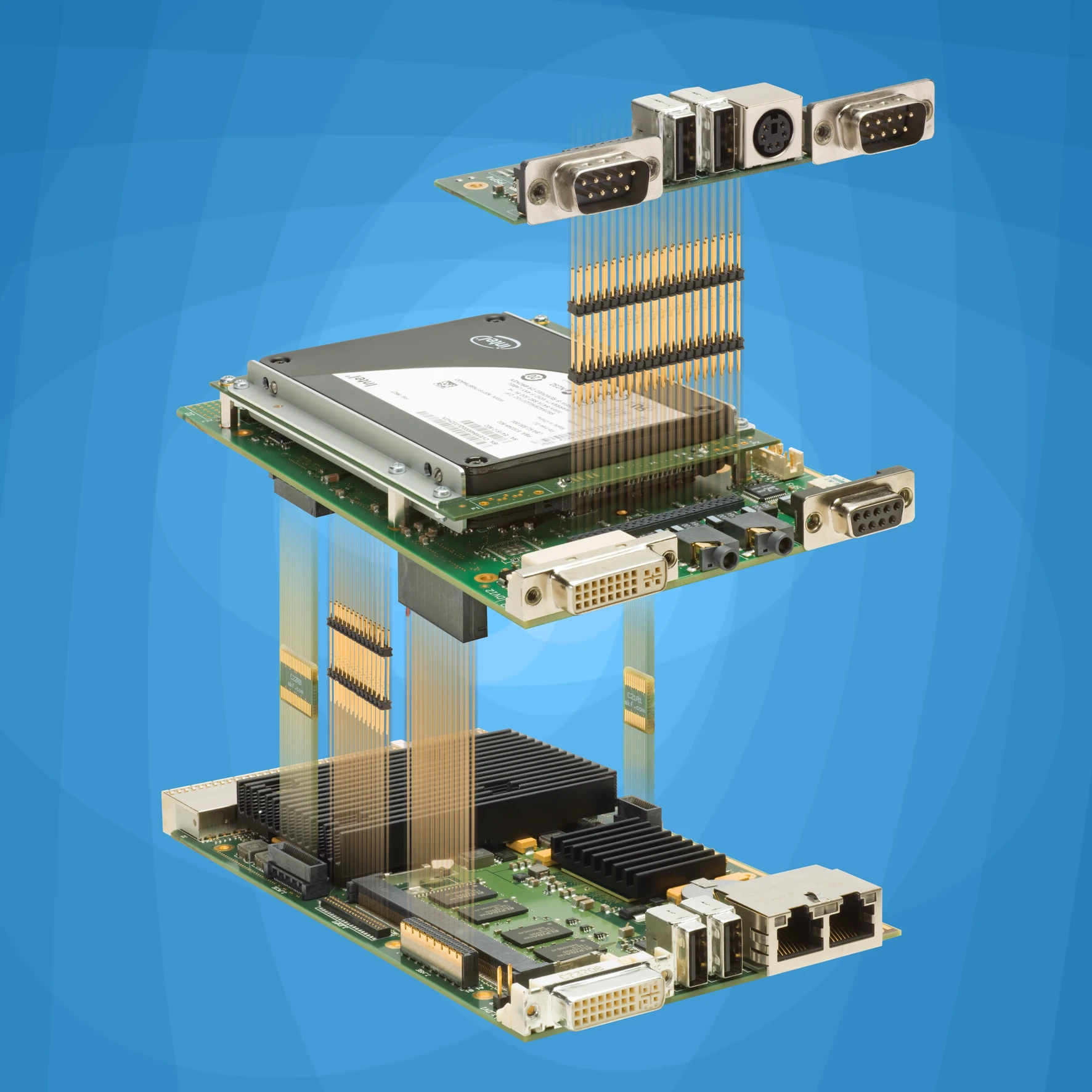
The CCM-BOOGIE is provided with a high performance mobile chipset (Intel® GS45) which operates at up to 1066MHz FSB and up to 1066MHz DDR3 memory clock for optimum system throughput. The chipset is based on PCI Express® technology and has a powerful integrated graphics accelerator. The DVI-I front panel connector enables dual screen video operation. Two Gigabit Ethernet controllers are provided for high speed connectivity (one of them IEEE 802.1as TimeSync compliant). The CCM-BOOGIE is equipped wit a set of local expansion interface connectors, which can be optionally used to directly attach a suitable (application specific) mezzanine side board, e.g. for audio- and legacy support, PCI Express based I/O circuitry, and a secondary DVI video output. Carrier board and side card come as a readily assembled 8HP unit typically. Most mezzanine cards can accommodate in addition a 2.5-inch drive. Also as an option, a suitable rear I/O transition module is available to the CCM-BOOGIE.
As a popular add-on option, the CCM-BOOGIE can be delivered with a small mezzanine module (C42-SATA), which accommodates a 1.8-inch SATA solid state drive (SSD). Alternatively, the C40-SCFA mezzanine card is provided with an industrial grade CompactFlash memory card, and/or an even more rugged USB Silicon State Drive (SSD). Both mezzanine modules fit into the 4HP envelope of the entire assembly.

Downloads & Ressources

Firmware

  • zipFirmware Update
  • TXT
    Release Notes

    ================================================
    Release Notes for Phoenix BIOS on EKF CCM-BOOGIE
    ================================================

    This file describes changes, extensions and bug fixes made in Phoenix BIOS
    for EKF CCM-BOOGIE. For any further questions contact EKF at:
    Email : support@ekf.de
    Internet : www.ekf.com

    =====================================================================================

    2014-01-10: BIOS release, Build #130 production

    – Improved detection of certain SATA devices (mainly SSDs) during POST

    – Updated MRC Version to V2.96

    – Added SMBIOS table entries for CompactPCI slots #9-15 and PCI devices #4-8

    – Show EKF as manufacturer in SMBIOS table “System Information”

    – Copied board serial number to SMBIOS table. This allows to show the serial
    number under an OS with appropriate tools (for Windows use tools like CPU-Z,
    SIW or others, for Linux use dmidecode).

    – Copied Board hardware version number to appropriate SMBIOS table

    – Show exact CPU type (Core 2 Duo P9300/L9400/U9300, Celeron 722/723) in BIOS Setup
    Setup [F2]: Main -> CPU Type:

    – Show board serial number in BIOS Setup
    Setup [F2]: Main -> Serial number

    – Show board manufacturing date in BIOS Setup
    Setup [F2]: Main -> Manufacturing Date:

    – Always show Usable Memory in BIOS Setup
    Setup [F2]: Main -> Memory usable:

    – Always show BIOS device (SPI Flash or FWH) in Setup
    Setup [F2]: Main -> BIOS loaded from:

    – Added Setup node to show CompactPCI bus type
    Setup [F2]: Main -> CPCI bus type -> [32|64] Bit bus detected

    – Added Setup node to show PLD Firmware Edition number
    Setup [F2]: Main -> PLD Firmware:

    – Setup node “State after Power-On” is now only changeable for CCM PLD Firmware Edition 0.
    For CCM PLD Firmware Editions >= 1 the node is displayed, but cannot be changed,
    because the board always goes to state S0 after G3.
    Setup [F2]: Advanced -> Board Configuration -> State after Power-On:

    – Added Setup option to execute a fixed delay at the early beginning of POST
    Setup (F2): Advanced -> Miscellaneous Configuration -> Execute Delay after Reset:
    Available options are: Disabled (i.e. no delay, Default), 1s, 4s or 12s
    If enabled, it allows certain devices to finish its internal initialization before
    POST has access to these devices. The delay is indicated by a red blinking LED GP
    in frontpanel of CCM-BOOGIE. Note: The old Setup option, which allows the execution
    of a 10s delay in the middle of POST, is removed.

    – Changed the generation of the GUID in SMBIOS table. The new algorithm ensures
    that the GUID is now really unique.

    – Removed switches for IGD enable/disable in BIOS Setup
    Setup [F2]: Advanced -> Miscellaneous Configuration

    – Added a check whether Rear-IO version of EKF CCM-BOOGIE is installed in a 64 bit
    CompactPCI system – which normally is not allowed! It could cause problems with
    USB overcurrent on Intel ICH9 UHCI port 2 (routed to CompactPCI J2).
    A new BIOS setup node controls whether a corresponding error message is shown:
    Setup [F2]: Advanced -> Miscellaneous Configuration -> Message if wrong bus detected:
    Available options:
    Disabled: Message not shown
    Enabled: Error message shown (Default)
    Regardless of mode setting, if in a CompactPCI 64 bit system and at beginning of
    POST an overcurrent at UHCI 2 is detected, any further detection of an overcurrent
    at this port during POST and during OS runtime is disabled.

    – Moved Setup node for Date and Time setting from menu Main to menu Advanced
    Setup [F2]: Advanced -> System Time/Date:

    =====================================================================================

    2013-07-19: BIOS release, Build #124 production

    – Added interrupt support (PIC and APIC) on CompactPCI for PCI devices 4-8

    =====================================================================================

    2013-05-31: BIOS release, Build #122 production

    – Added Setup option to enable a patch for PCI BARs which requests >= 1GB of Memory
    Setup (F2): Advanced -> PCI Configuration -> Patch for big PCI BARs
    Available options are: Disabled (Default), Enabled

    =====================================================================================

    2013-03-22: BIOS release, Build #120 production

    – Added Setup option to expand IO space for CompactPCI to 0xFFFF
    Setup (F2): Advanced -> PCI Configuration -> Expand IO Space for CompactPCI
    Available options are: Disabled (Default), Enabled

    =====================================================================================

    2012-12-03: BIOS release, Build #118 production

    – Added Setup option which allows to select retry mode if Boot failed at end of POST
    Setup (F2): Advanced -> Miscellaneous Configuration -> Select Mode after Boot failed
    Available options are: Key (Default), Retry BS, Warm Restart, Cold Restart
    Key: BIOS waits for any key press before it retries the Boot Sequence
    Retry BS (Boot Sequence): After two seconds BIOS retries the Boot Sequence
    Warm Restart: BIOS Warmstart (jump to FFFF:0)
    Cold Restart: BIOS Coldstart with on-board power cycle (0Eh -> CF9h)

    =====================================================================================

    2012-07-16: BIOS release, Build #116 production

    – Forced disabling of PS/2 keyboard and mouse swap function of SIO SCH 3114. This is
    necessary cause the swap function is sometimes not disabled after Reset or Power Up.

    =====================================================================================

    2012-06-22: BIOS release, Build #114 production

    – Fixed issue that BIOS hangs for some minutes if Intel SATA controller is set to disabled

    – SATA devices on Intel SATA controller are now numbered S1, S2, S3 and S4

    – Added support to prevent Intel SATA devices to be inserted in boot list. This is useful
    in cases when a new installed SATA device will be automatically moved to a higher position
    in boot list, compared with the position of the current boot device. To avoid this set
    the following option for the new inserted SATA device to ‘Disabled’:
    Setup [F2]: Advanced -> ATA/IDE Configuration -> Intel ICHx ATA Configuration ->
    -> SATA Port [1-4] -> Boot from Device:
    Available options are: Disabled, Enabled (Default)

    – Added support for fast DDR3 SDRAM modules on ULV version (1.2GHz) of EKF CCM-21xx-BOOGIE.
    Such SDRAM modules (e.g. VIKING PC3-10600) could not be used on ULV version of CCM-BOOGIE,
    cause they are only specified for CAS latencies greater than 7. This has been fixed.

    – MRC version number changed to V2.9.5

    – Changed RTC default date to 2012-01-01

    =====================================================================================

    2011-05-12: BIOS release, Build #110 production

    – Added support for new JMB362 controller chip revision C

    – Changed legacy IRQ number in SIO SCH3114 configuration for serial port 4.
    This prevents IRQ sharing on serial ports 2 and 4 under Windows XP.

    – Show MAC addresses of Ethernet controller 1 and 2 in Setup
    Setup [F2]: Advanced -> Ethernet Configuration

    – Changed BIOS Setup option for remote boot via Ethernet. Now only one Setup option
    exists, which selects Ethernet Controller for remote boot with Intel PXE:
    Setup [F2]: Advanced -> Ethernet Configuration -> Select Eth-Ctrl for PXE Boot:
    Available options: Disabled (Default), Eth 1 (top RJ45), Eth 2 (bottom RJ45)

    – Changed RTC default date to 2011-01-01

    =====================================================================================

    2011-04-13: BIOS release, Build #108 production

    – Added ACPI support for serial port of on-board SIO IT8761E. This on-board serial
    port is mapped to COM1 (Windows OS) if no external SIO SCH3114 is detected.

    – If SIO of type SMSC SCH3114 is detected, the four serial ports of SCH3114 are mapped
    to COM[1-4] (Windows OS) and on-board serial port becomes COM5 (Windows OS).

    – If serial ports are disabled in BIOS Setup, they are now also disabled in ACPI-OS
    Setup [F2]: Advanced -> I/O Device Configuration -> On-Board SIO Configuration (IT8761E)
    Setup [F2]: Advanced -> I/O Device Configuration -> External SIO Configuration (SMSC SCH3114)

    – If SIO of type SMSC SCH3114 is not detected, settings can now not be changed in BIOS Setup
    Setup [F2]: Advanced -> I/O Device Cofiguration -> External SIO Configuration (SMSC SCH3114)

    – If SIO of type SMSC SCH3114 is not detected, FDC controller is inactived in ACPI

    – Changed behaviour of LED GP (lights Red, Green or Orange) in front panel of CCM:
    – A red blinking LED GP indicates: BIOS has not started (-> Board Failure)
    – LED GP off immediately after Reset indicates a successful BIOS start
    – Approximately one second after Reset green LED GP is switched on to indicate
    start of Legacy BIOS
    – If the keyboard is ready for F2 key (BIOS Setup) or F11 key (Boot Menu) orange
    LED GP is switched on (orange means red LED along with green LED). This eases
    the timing of F2/F11 key press, cause some displays need too much time for their
    own initialization (i.e. they are not yet able to show messages sent from POST).
    – Green LED GP is switched on again before BIOS Setup.
    – Green LED is switched off immediately before Boot

    – Modified initialization of LM87 hardware monitor. This supports monitoring tools
    which do not initialize this controller (like SpeedFan for Windows).

    =====================================================================================

    2011-01-27: BIOS release, Build #106 production

    – Fixed a bug which crashed the BIOS if a board with a PCI Bridge of type PLX PCI9050
    is installed

    =====================================================================================

    2011-01-14: BIOS release, Build #104 production

    – Added Setup option to control CPU C-States (CPU low power modes)
    Setup (F2): Advanced -> CPU Configuration -> C-States
    If set to Enabled (Default) four more Setup options allow fine-tuning of C-States:
    Setup (F2): Advanced -> CPU Configuration -> Enhanced C-States
    Setup (F2): Advanced -> CPU Configuration -> Deep C4-State
    Setup (F2): Advanced -> CPU Configuration -> Hard C4-State
    Setup (F2): Advanced -> CPU Configuration -> C6-State
    All options above are enabled by default for maximum power reduction when CPU is idle.

    – Added Setup option to control generation of ACPI table for CPU throttling states
    Setup (F2): Advanced -> CPU Configuration -> T-States
    Setup option is enabled by default.

    – Added BIOS Password feature
    Setup (F2): Advanced -> BIOS/POST Configuration -> Set Supervisor Password:
    If Password is enabled, next time BIOS Setup can only be entered if the correct
    Password is typed in. Note: the Password will be immediately enabled after typed in,
    i.e. it is not necessary to save it with F10 (Save and Exit).

    – Added Setup option to allow that an OS can only boot, if the correct Password is
    typed in
    Setup (F2): Advanced -> BIOS/POST Configuration -> Password on Boot:
    Available options are: Disabled (Default), Enabled
    This Setup option is only available if a Password was previously set.

    =====================================================================================

    2010-12-02: BIOS release, Build #100 production

    – Fixed a bug caused by #098 which disables PCI Express bus at ICH9

    =====================================================================================

    2010-11-29: BIOS release, Build #098 production

    – Removed a bug (boot process hangs) if no EKF expansion board is installed and if no
    keyboard is attached

    =====================================================================================

    2010-05-21: BIOS release, Build #096 production

    – Integrated a new DXE driver for PS2 keyboard, which does not show the nine minute
    delay before boot

    – Disabled support for external graphics boards. External graphic not yet supported.

    – Added support for Intel ICH9 AHCI Native BIOS

    – Added Setup option to allow setting of max speed for Intel ICH9 SATA ports
    Setup (F2): Advanced -> ATA/IDE Configuration -> Intel ICHx ATA Configuration
    -> SATA AHCI Max Speed:
    Available options: 1.5Gb/s or 3.0Gb/s

    – SATA port 4 now labeled as an internal port, like ports 1-3

    =====================================================================================

    2010-03-25: BIOS release, Build #094 production

    – Disabled PS/2 keyboard support to avoid a 9 minute delay at end of POST if no
    keyboard (USB or PS/2) is attached

    – Enabled Setup option to control an ACPI table for Intels High Precision Event Timer
    Setup (F2): Advanced -> ACPI Configuration -> HPET Support:
    Available options: Disabled, Enabled (Factory Default)
    Four different base addresses can be selected:
    Setup (F2): Advanced -> ACPI Configuration -> HPET Base Address:
    Default base address is 0xFED00000.
    More info about HPET: http://www.intel.com/hardwaredesign/hpetspec_1.pdf

    – Removed ACPI thermalzone TZ00, moved ACPI thermalzone TZ01 to thermalzone TZ00

    =====================================================================================

    2010-03-09: BIOS release, Build #092 production

    – Added Setup option to load Intel PXE BIOS for ICH-internal LAN-Controller 82567:
    Setup (F2): Advanced -> Ethernet Configuration -> PXE BIOS for Ethernet Ctrl 1:
    Available options: Disabled (Factory Default), Enabled

    – Added Setup option to load Intel PXE BIOS for Ethernet Controller Intel 82574:
    Setup (F2): Advanced -> Ethernet Configuration -> PXE BIOS for Intel 82574:
    Available options: Disabled (Factory Default), Enabled
    This Setup option is only visible if Ethernet controller 1 is disabled, cause only
    the first Intel Ethernet controller found during POST can be used for remote
    booting.

    – Added feature to load PXE Ethernet Expansion ROM after any other (external)
    Expansion ROM has been loaded. This is sometimes necessary, if a OS installation to
    a SCSI harddisk or to a SATA device should be made from a remote (Ethernet) device.
    This feature can be controlled with new option:
    Setup (F2): Advanced -> Ethernet Configuration -> Load Ethernet ROM late:
    If set to Enabled, Ethernet Expansion ROMs are loaded after a SCSI BIOS (EKF CS3
    or CS5) or after a SATA BIOS (EKF CE5-CADENZA) has been loaded.

    =====================================================================================

    2010-02-26: BIOS release, Build #090 production

    – Extended JMB363 support with two different Expansion ROMs
    Setup (F2): Advanced -> ATA/IDE Configuration -> [1-4]. JMicron JMB363 Configuration
    -> Expansion ROM for JMB36x:
    Options:
    Disabled: No Expansion ROM for JMB36x is loaded
    V1.06.75: Load Expansion ROM V1.06.75. Supports PCI class codes IDE, RAID and AHCI,
    which can be selected in BIOS setup
    V1.07.00: Load Expansion ROM V1.07.00. Supports class codes RAID and AHCI
    See JMicron release notes for differences between ROM versions:
    ftp://driver.jmicron.com.tw/jmb36x/Option_ROM/release%20note.txt

    – Changed default boot sequences (1-4) to EKF standard

    – Added keys ‘-‘ and ‘+’ and Ctrl-Up and Ctrl-Down for moving devices up and down
    in Boot menu

    – Added check of valid data in configuration EEPROM. If unvalid data is detected, red
    error message “028C: Config EEPROM contains bad data” is shown during POST

    – Added feature to reduce GS45 power consumption. This can be controlled with a new
    Setup node:
    Setup (F2): Advanced -> Graphics Device Configuration -> On-Board Graphics
    Configuration -> GFX Low Power Mode:
    If set to ‘Enabled’, GS45 graphics render clock speed is reduced from 533MHz to
    320MHz, which in turn reduces power consumption. Default mode is ‘Disabled’, which
    means GS45 graphics controller renders with max speed (533MHz).

    – Updated MRC to Rev 2.91

    – Added detection of JMB362 behind PLX 8614 bridge on EKF PCJ-JAM

    – Fixed a bug which prevents detection of newer Cherry keyboards (POST Message
    ‘Keyboard Error’)

    =====================================================================================

    2009-11-13: BIOS release, Build #086 production

    – Updated ACPI strings in ACPI setup nodes

    – Added code to set EKF SSVID (E4BFh) and CCM SSID (CC4Dh) to all PCI devices
    integrated in Intel chipset (GS45 and ICH9)

    – Added support for SPIs of type EON EN25Q16

    – Added code to enable or disable ICH9 internal PCI SATA controller:
    Setup (F2): Advanced -> ATA/IDE Configuration -> Intel ICHx ATA Configuration
    -> On-board SATA interface:
    Sometimes it is useful to disable Intel SATA controller if an OS installation
    is made on SATA drives attached to JMB36x controller.
    Default mode is ‘Enabled’.

    – Added support for SATA controller JMB362

    – Added support to boot from SATA controller JMB362 or JMB363

    – Added setup option which allows to enable a delay (about 10-12s) after Power-Up
    Setup (F2): Advanced -> Miscellaneous Configuration -> Execute Delay after Reset:
    This option can be used to possibly solve Power-Up problems of some devices.

    =====================================================================================

    2009-09-25: BIOS release, Build #084 production

    – Added setup node to enable or disable Dynamic FSB:
    Setup (F2): Advanced -> Board Configuration -> Dynamic FSB
    Dynamic FSB is enabled per default.

    – Disabled GFX Low-Power mode. This workarounds a bug located in Intel MRC code
    (memory initialization) until version 2.9

    – Fixed a bug which prohibits usage of serial ports 3 and 4 on EKF expansion boards

    – Added ACPI support for serial ports 1-4 on EKF expansion boards (SIO SCH3114)

    – Fixed a bug when initializing ISP local option register. This occured only if
    CMOS has bad data (e.g. after board production or battery exchange).

    =====================================================================================

    2009-07-23: First BIOS release, Build #082 production

    =====================================================================================

    < End of File >

Suitable Carrier Cards

Mezzanine Side Cards

Specifications

  • Single size CompactPCI style Eurocard (160x100mm2), front panel width 4HP (20.3mm)

Simplified Block Diagram
CCM-BOOGIE BLOCKDIAGRAMM
Contact Us